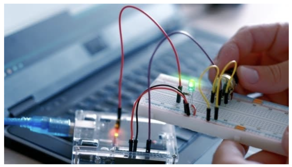
What is Arduino
Arduino is an open-source electronics platform based on easy-to-use hardware and software.
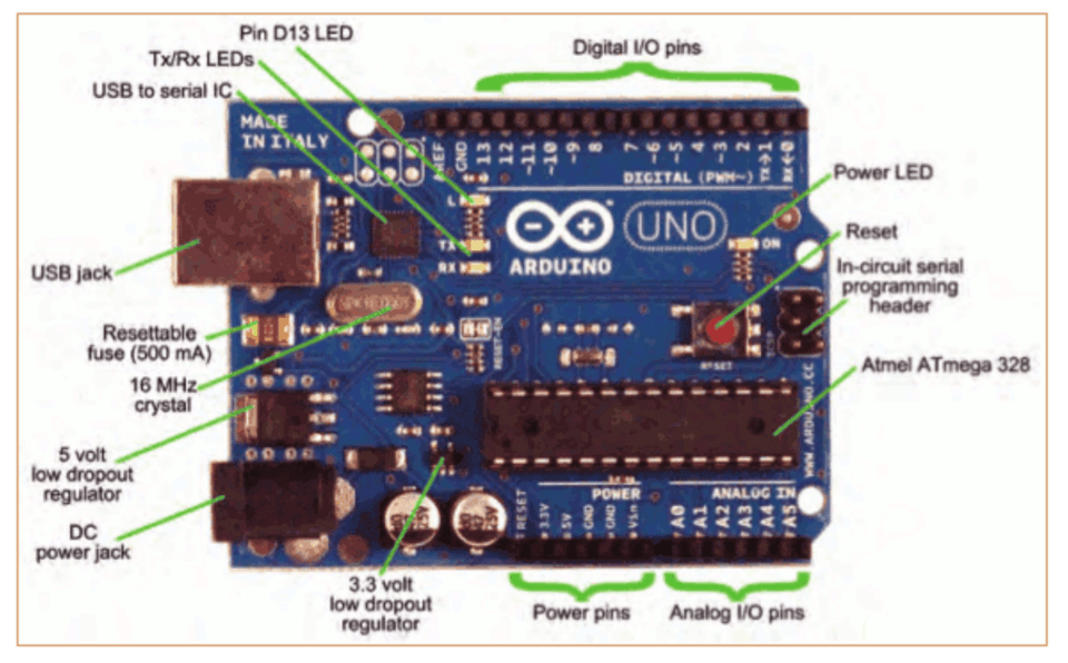
The Arduino platform includes a range of microcontroller boards that come in different sizes and shapes
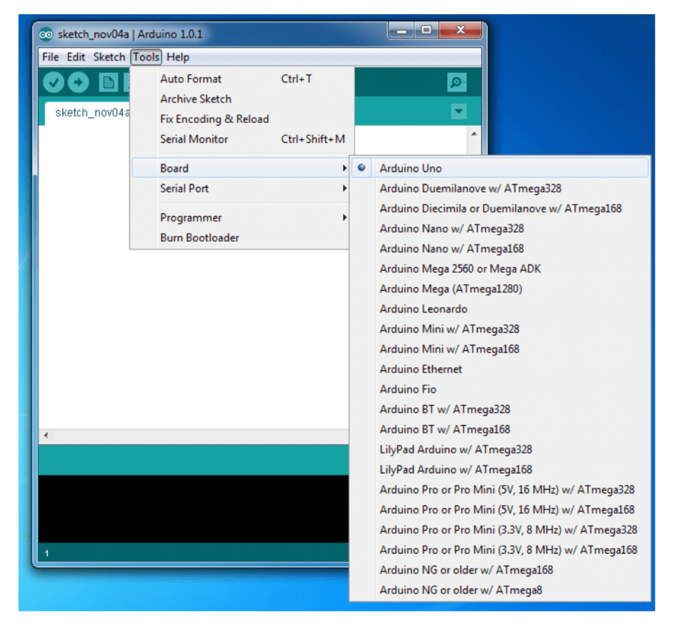
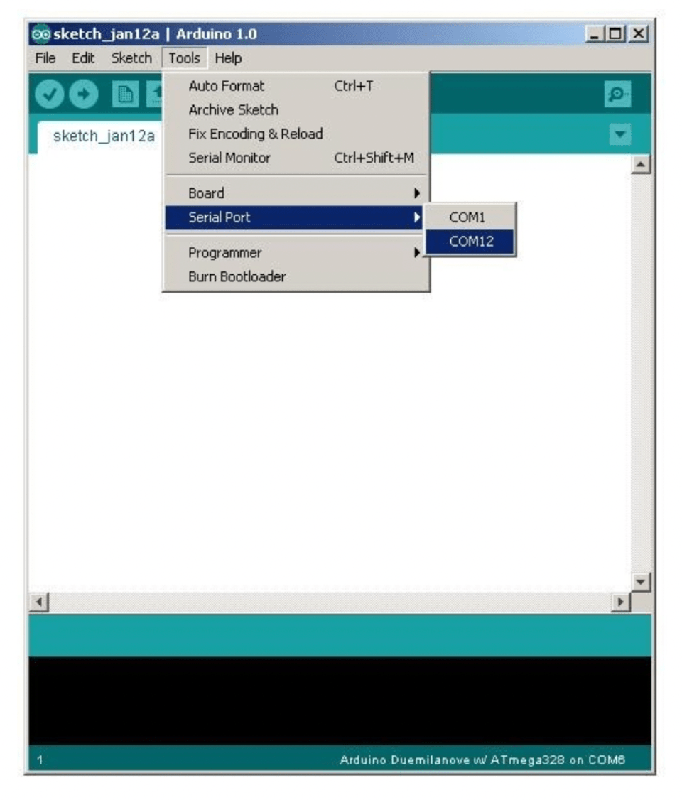
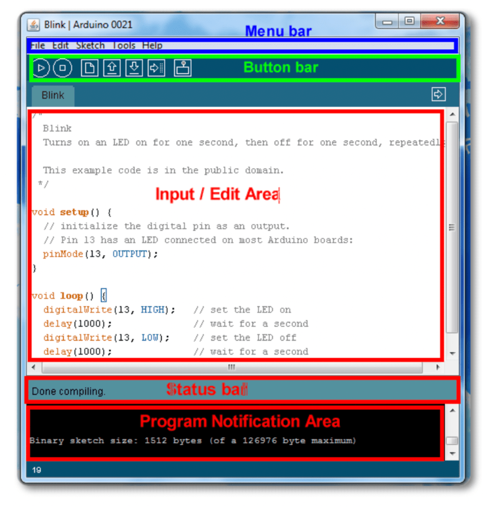
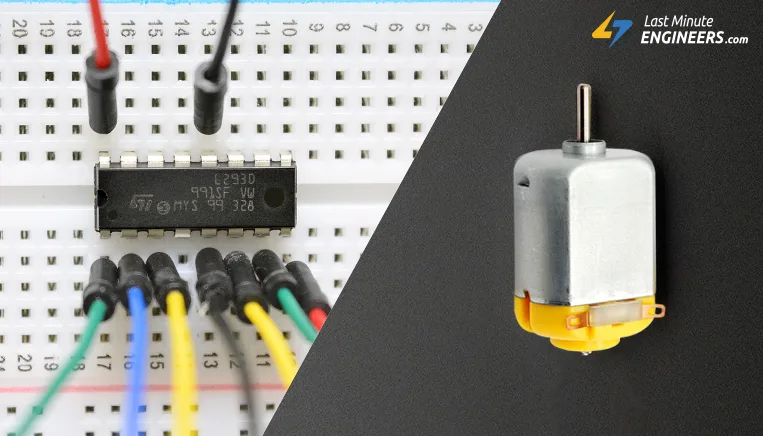
These boards are equipped with digital and analog input/output pins, which can be used to connect to various sensors, motors, lights, and other electronic components. The Arduino boards are programmed using the Arduino Integrated Development Environment (IDE), which is a free, open-source software tool that runs on Windows, Mac OS X, and Linux.
Arduino is a great tool to introduce to kids because it provides an accessible and interactive way to learn about electronics and programming
Easy to use: Arduino is designed to be easy to use, even for beginners. The hardware is straightforward to connect, and the software is easy to learn.
Interactive: Arduino allows kids to create interactive projects that respond to the environment around them. This can be a great way to engage their curiosity and creativity.
Versatile: Arduino can be used for a wide range of projects, from simple LED lights to complex robotics. This versatility allows kids to explore different aspects of electronics and programming.
Open source: Arduino is an open-source platform, meaning that the hardware and software are freely available for anyone to use, modify, and distribute. This makes it an excellent platform for kids to learn about the principles of open-source technology and collaboration.
Fun: Above all, Arduino can be a lot of fun! Kids can create their projects and experiment with different components to see what works best. This can be a rewarding and engaging way to learn about electronics and programming.
WHY KIDS SHOULD LEARN ARDUINO
Over the years, Arduino has served as the base of several scientific inventions. It is used daily by programmers, professionals, scientists, instructors, and students alike. Arduino is cheap, easy to use, and operates on an open source system. Here are the reasons why kids are encouraged to learn with Arduino.
Why its important to introduce kids with problem-solving, critical thinking, and creativity
Overall, Arduino can be an excellent tool for introducing kids to electronics and programming. It can help them develop important skills such as problem-solving, critical thinking, and creativity, while also fostering a sense of curiosity and wonder about the world around them.
Introducing kids to problem-solving, critical thinking, and creativity is important because these are essential skills that will serve them well throughout their lives, regardless of what career or field they choose to pursue. Here are some reasons why these skills are so important:
Problem-solving: Problem-solving is the ability to identify, analyze, and solve problems. This skill is essential in both personal and professional life, as it allows us to find solutions to challenges that we face. By introducing kids to problem-solving, we can help them develop a systematic and logical approach to solving problems, which can be applied in many areas of life.
Critical thinking: Critical thinking is the ability to analyze information, evaluate arguments, and draw conclusions. It involves questioning assumptions, considering different perspectives, and making reasoned judgments. This skill is crucial for making informed decisions, and for distinguishing between fact and opinion. By introducing kids to critical thinking, we can help them become more discerning and thoughtful individuals.
Creativity: Creativity is the ability to generate new and original ideas, and to express them in innovative ways. This skill is important because it enables us to think outside the box and come up with fresh solutions to problems. By introducing kids to creativity, we can help them develop their imagination and foster a sense of curiosity and wonder.
Overall, by introducing kids to problem-solving, critical thinking, and creativity, we can help them develop the skills they need to navigate the complexities of the modern world. These skills can help them become more adaptable, resilient, and successful in their personal and professional lives.
What is an Arduino kit?
An Arduino kit is made up of various components for creating devices and gadgets, such as robots, remote controls, home appliances, etc.
With an Arduino kit, kids can learn various programming languages, including engineering, science, and robotics.
What Programming Language do Arduino Kits use?
Arduino has its own programming language, called the Arduino programming language. Arduino programming language is similar to C++.
However, Arduino kits can also function well with C, C++, and Python programming languages.
Are Arduino Kits easy for kids?
Arduino kits are designed with kids in mind, and they are perfectly suitable for kids. Kids aged 7 and above can use Arduino kits.
FINAL THOUGHTS ABOUT ARDUINO FOR KIDS
As parents, you can invest in your kids' growth and career with Arduino course. Arduino cuts across both hardware and software, as well as all areas of Science, Technology, Engineering, and Mathematics (STEM). Kids can learn how to create and control robots with Arduino Robotics kits.
Kids can also be introduced to the basic concepts of coding with Arduino. Beyond the conventional programming languages for kids, they can also learn about the Arduino programming language and how it works.