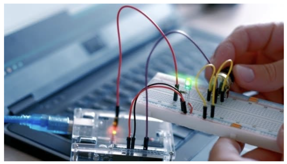
When we work on Arduino we typically use Arduino IDE (Integrated development environment), which is software that's available for all major computers which provide a text editor for writing code with integrated library support and a physical programmable circuit board to run the code.
The Arduino programming language is a modified version of C/C++. Usually, we program in C++ with the addition of methods and functions. A program written in Arduino programming language is called sketch and saved with .ino extension. You can even use Python to write an Arduino program. All these languages are text-based programming languages.
To reduce the complexity and maximize the interest of students we do have some online simulators where we don't have to buy or download anything.
Is Arduino good for beginners?
Yes, Arduino is good for beginners. There are many electronic boards out there. Why use Arduino for beginners? Well, there are few points that make this microcontroller unique:
Whenever we are going to buy something, we should always look at the cost first. Arduino is cost-effective and easily accessible.
Arduino is easier to learn as a programming language as it is a simplified version of the C++ programming language.
Arduino is cross-platform which makes it easy to run on any sort of device compared to other microcontrollers which can only run on Windows.
Arduino has many variations available to choose from, you can easily choose according to your need.
Explore a step-by-step guide to setup the environment of Arduino programming
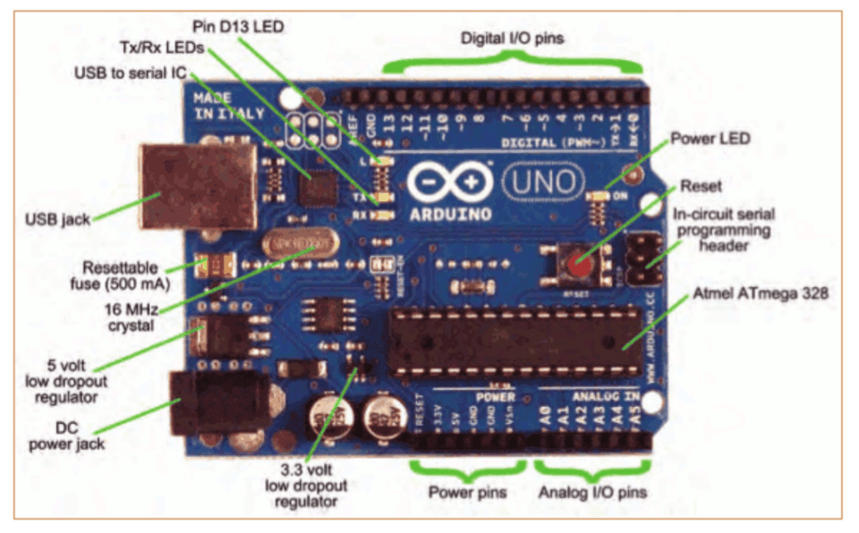
Here's how to use the physical Arduino Uno board. The Arduino Uno is one among the several development boards. It has 14 digital input/output pins, 6 analog input pins, a power jack, a reset button, a USB connection, an ICSP header.
1. Download & install the Arduino environment (IDE)
If you just got your Arduino Uno board, you’ll first have to install the Arduino IDE (Integrated Development Environment) on another computer. The code is typed into the IDE and sent to the Arduino via a USB cable.
Visit arduino.cc to download the most recent Arduino IDE version for your computer. There are different versions for Mac, Windows, and Linux OS.
At the download page, click on the “Installer” option for the easiest installation then
Save the .exe file to your disk drive.
Open the .exe file.
Click the button to agree to the licensing agreement
Decide which components to put in, then click “Next”
Select which folder to put in the program to, then click “Install”
Wait for the program to complete installing, then click “Close”
2. Launch the Arduino IDE
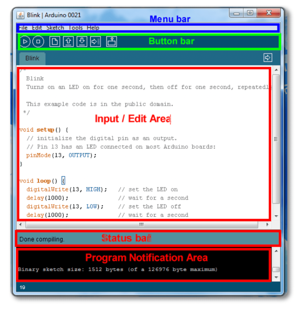
After your Arduino IDE software is downloaded, unzip the folder. To do so, double-click on the Arduino shortcut on your Desktop. The IDE will open up and you’ll see the code editor.
3. If needed, install the drivers
If you used the Installer, it'll install drivers automatically as soon as you connect your board.
4. Connect the board to your computer via the USB cable
To power up your board, connect your Arduino board with the pc via USB cable. The green color power LED should glow on the board.
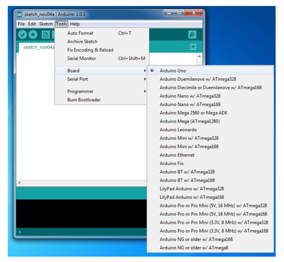
5. Select your board
Next, make sure the software is ready up for your particular Arduino board. Go to the “Tools” computer menu from the menu bar. Select the “Board” option and another menu will appear, where you'll select your Arduino model from the list.
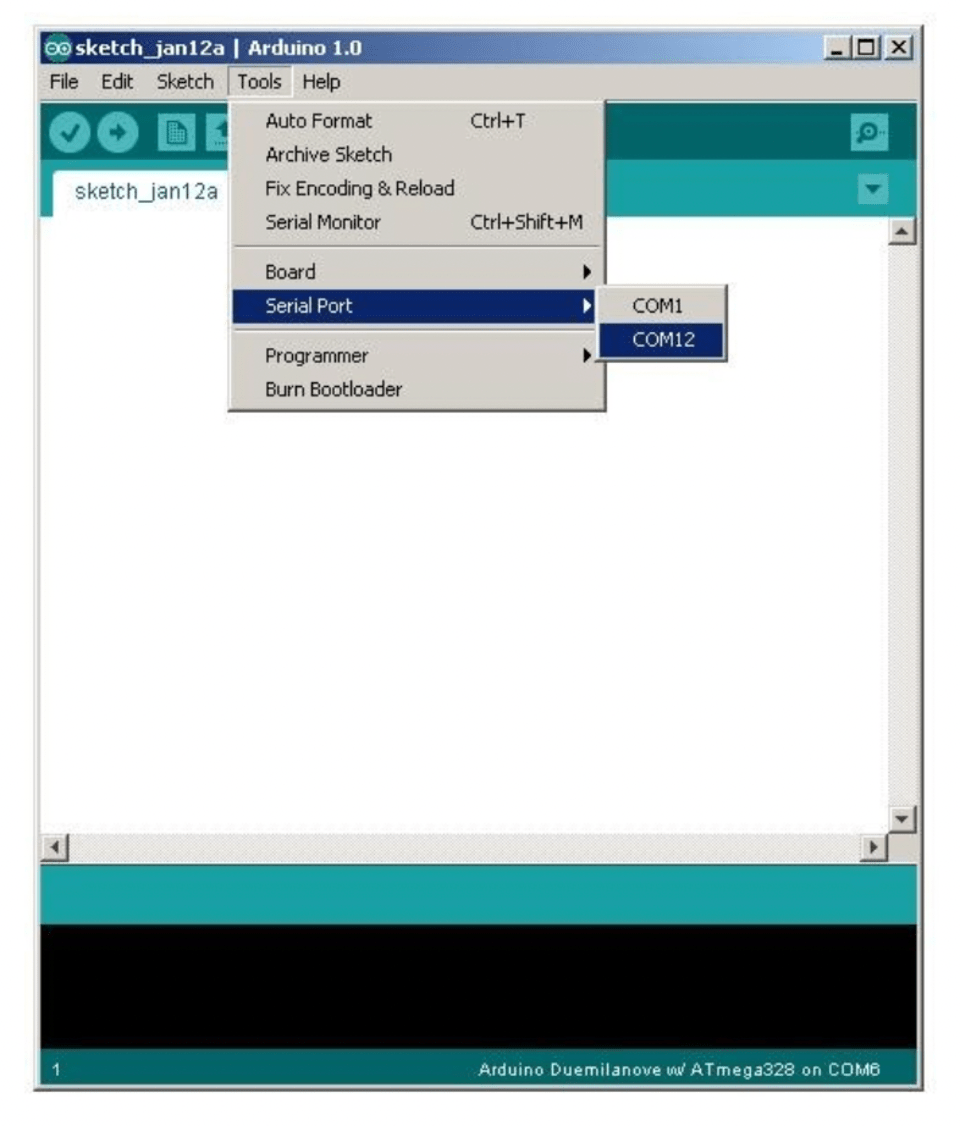
6. Select your serial port
Select the serial device of the Arduino board. Go to Tools, and then the serial port menu. You might see COM3 or higher (COM1 and COM2 are usually reserved for hardware serial ports). To find out which port your Arduino board is connected to, disconnect your Arduino board and re-open the menu. The entry that disappears should be the Arduino board. Reconnect the board and choose that serial port.
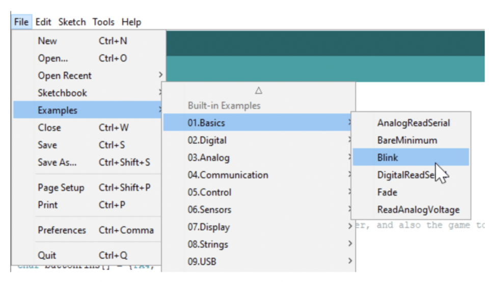
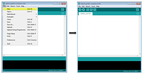
7. Open the blink example
We'll start with the LED Blink example that comes with the Arduino IDE. Just go to File->Examples->Basics->Blink.
Here are the few things to keep in mind while writing the code:
Code is case sensitive
All the statements must end with a semicolon
Comments follow a // or begin with /* and end with */
Void loop() and void setup() are two mandatory functions. The setup section of the code is simply run once when the Arduino board is first turned on or reset. Once the setup is complete, the loop runs over and over. It keeps on running until the board continues to stay powered.
The status bar shows that the program is compiled or uploaded.
Program notification area shows error(s) within the code if any.
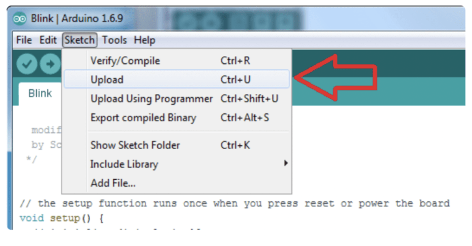
8. Upload the program
Now it is time to upload your first sketch(code). Confirm the Arduino is plugged in, and the green light is on - therefore the correct board and port is chosen. Select Upload from the Sketch drop-down menu.
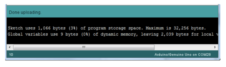
After a few seconds, you will get this screen, with the message "Done uploading."
How to Use the L293D Motor Driver - Arduino Tutorial
Introduction: How to Use the L293D Motor Driver - Arduino Tutorial
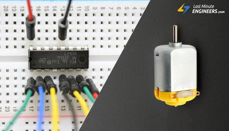
The L293D is a 16-pin Motor Driver IC which can control a set of two DC motors simultaneously in any direction. The L293D is designed to provide bidirectional drive currents of up to 600 mA (per channel) at voltages from 4.5 V to 36 V (at pin 8!). You can use it to control small dc motors - toy motors. Sometimes it can be extremely hot.
In this tutorial you will learn how to use it with Arduino uno to control two dc motors.
Step 1: What You Will Need
For this project you will need:
Arduino uno
Breadboard
L293D Motor Driver IC
2x (small) DC motors
Step 2: The Circuit
The connections are easy, see the image above with the breadboard circuit schematic.
Tip: You can connect an external power source to L293D pin 8, up to 36V! Make sure not to "burn" your motors!
Step 3: The Code
Here's the code, embedded using codebender!
Try downloading the codebender plugin and clicking on the Run on Arduino button to program your Arduino with this sketch. And that's it, you've programmed your Arduino board!
You can keep playing with that by clicking the "Edit" button and start making your own modifications to the code. For example try to combine parts of code to move both motors simultaneously.
Try to use analogWrite(pin, PWM value) instead digitalWrite(pin, HIGH/LOW) to control the speed of motors!
Step 4: Well Done!
You have successfully completed one more Arduino "How to" tutorial and you learned how to use the L293D motor driver IC to control two dc motors with the Arduino uno board.
I hope you liked this, let me know in the comments. There will be more of them, so make sure to click Follow button!
Control DC Motors with L293D Motor Driver IC & Arduino
If you’re planning on assembling your new robot friend, you’ll eventually want to learn how to control DC motors. The easiest and inexpensive way to control DC motors is to interface the L293D Motor Driver IC with the Arduino. It can control both the speed and the spinning direction of two DC motors.
And as a bonus, it can also control a unipolar stepper motor like the 28BYJ-48 or a bipolar stepper motor like the NEMA 17.
Controlling a DC Motor
To have complete control over DC motor we have to control its speed and rotation direction. This can be achieved by combining these two techniques.
PWM – to control speed
H-Bridge – to control the rotation direction
PWM – to control speed
The speed of a DC motor can be controlled by changing its input voltage. A common technique to do this is to use PWM (Pulse Width Modulation).
PWM is a technique where the average value of the input voltage is adjusted by sending a series of ON-OFF pulses.
Technical Specifications
Here are the specifications:
Motor output voltage
4.5V – 36V
Logic input voltage
5V
Output Current per channel
600mA
Peak Output Current per Channel
1.2A
For more details, please refer below datasheet.
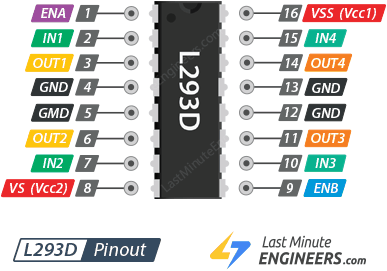
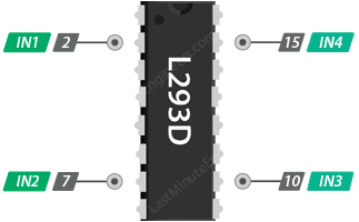
L293D Motor Driver IC Pinout
The L293D IC has a total of 16 pins that connect it to the outside world. The pinout is as follows:
Let’s get acquainted with all the pins one by one.
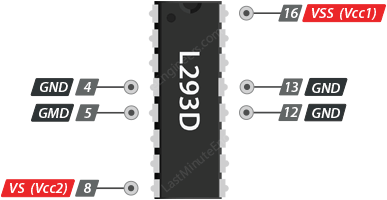
Power Pins
The L293D motor driver IC actually has two input power pins – VS and VSS.
VS (Vcc2) pin gives power to the internal H-Bridge of the IC to drive the motors. You can connect an input voltage anywhere between 4.5 to 36V to this pin.
VSS (Vcc1) is used to drive the internal logic circuitry which should be 5V.
GND pins are common ground pins. All 4 GND pins are internally connected and used to dissipate the heat generated under high load conditions.
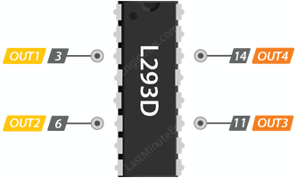
Output Pins
The L293D motor driver’s output channels for the motor A and B are brought out to pins OUT1,OUT2 and OUT3,OUT4 respectively. You can connect two 5-36V DC motors to these pins.
Each channel on the IC can deliver up to 600mA to the DC motor. However, the amount of current supplied to the motor depends on system’s power supply.
Direction Control Pins
By using the direction control pins, you can control whether the motor rotates forward or backward. These pins actually control the switches of the H-Bridge circuit inside the L293D IC.
The IC has two direction control pins for each channel. The IN1 and IN2 pins control the spinning direction of motor A; While IN3 and IN4 control the spinning direction of motor B.
The spinning direction of the motor can be controlled by applying logic HIGH (5V) or logic LOW (Ground) to these inputs. The chart below shows how this is done.
IN1
IN2
Spinning Direction
Low(0)
Low(0)
Motor OFF
High(1)
Low(0)
Forward
Low(0)
High(1)
Backward
High(1)
High(1)
Motor OFF
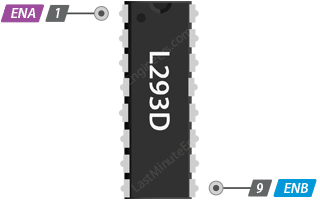
Speed Control Pins
The speed control pins ENA and ENB are used to turn on/off the motors and control its speed.
Pulling these pins HIGH will cause the motors to spin, while pulling it LOW will stop them. But, with Pulse Width Modulation (PWM), you can actually control the speed of the motors.
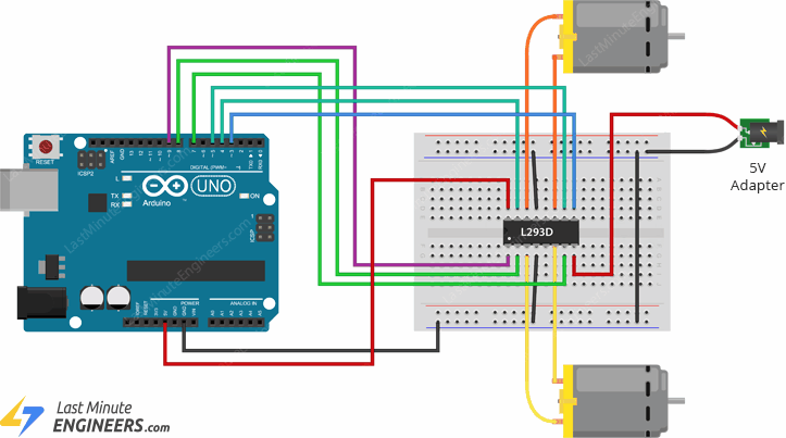
Wiring a L293D Motor Driver IC to an Arduino
Now that we know everything about the IC, we can start connecting it to our Arduino!
Let’s start by connecting the power supply to the motors. In our experiment we are using DC gearbox motors (also known as ‘TT’ motors) commonly found in two-wheel-drive robots. They are rated for 3 to 12V. Therefore, we will connect the external 5V power supply to the VS (Vcc2) pin.
Next, we need to supply 5V to the logic circuitry of the L293D. Connect the VSS (Vcc1) pin to the 5V output on the Arduino. And make sure your circuit and Arduino share a common ground.
Now connect the L293D IC’s Input and Enable pins (ENA, IN1, IN2, IN3, IN4 and ENB) to the six Arduino digital output pins (9, 8, 7, 5, 4 and 3). Note that Arduino output pins 9 and 3 are both PWM-enabled.
Finally, connect one motor to OUT1 and OUT2 and the other motor to OUT3 and OUT4. You can interchange the connections of your motor. There is technically no right or wrong way.
When you are done you should have something that looks similar to the illustration shown below.
Arduino Example Code
The following sketch will give you a complete understanding on how to control the speed and spinning direction of a DC motor with the L293D motor driver IC and will serve as the basis for more practical experiments and projects.
// Motor A connectionsint enA = 9;
int in1 = 8;
int in2 = 7;
// Motor B connectionsint enB = 3;
int in3 = 5;
int in4 = 4;
voidsetup() {
// Set all the motor control pins to outputspinMode(enA, OUTPUT);
pinMode(enB, OUTPUT);
pinMode(in1, OUTPUT);
pinMode(in2, OUTPUT);
pinMode(in3, OUTPUT);
pinMode(in4, OUTPUT);
// Turn off motors - Initial statedigitalWrite(in1, LOW);
digitalWrite(in2, LOW);
digitalWrite(in3, LOW);
digitalWrite(in4, LOW);
}
voidloop() {
directionControl();
delay(1000);
speedControl();
delay(1000);
}
// This function lets you control spinning direction of motorsvoiddirectionControl() {
// Set motors to maximum speed// For PWM maximum possible values are 0 to 255analogWrite(enA, 255);
analogWrite(enB, 255);
// Turn on motor A & BdigitalWrite(in1, HIGH);
digitalWrite(in2, LOW);
digitalWrite(in3, HIGH);
digitalWrite(in4, LOW);
delay(2000);
// Now change motor directionsdigitalWrite(in1, LOW);
digitalWrite(in2, HIGH);
digitalWrite(in3, LOW);
digitalWrite(in4, HIGH);
delay(2000);
// Turn off motorsdigitalWrite(in1, LOW);
digitalWrite(in2, LOW);
digitalWrite(in3, LOW);
digitalWrite(in4, LOW);
}
// This function lets you control speed of the motorsvoidspeedControl() {
// Turn on motorsdigitalWrite(in1, LOW);
digitalWrite(in2, HIGH);
digitalWrite(in3, LOW);
digitalWrite(in4, HIGH);
// Accelerate from zero to maximum speedfor (int i = 0; i < 256; i++) {
analogWrite(enA, i);
analogWrite(enB, i);
delay(20);
}
// Decelerate from maximum speed to zerofor (int i = 255; i >= 0; --i) {
analogWrite(enA, i);
analogWrite(enB, i);
delay(20);
}
// Now turn off motorsdigitalWrite(in1, LOW);
digitalWrite(in2, LOW);
digitalWrite(in3, LOW);
digitalWrite(in4, LOW);
}
Code Explanation:
The Arduino code is pretty straightforward. It doesn’t require any libraries to work. The sketch begins with declaring the Arduino pins to which the L293D’s control pins are connected.
// Motor A connectionsint enA = 9;
int in1 = 8;
int in2 = 7;
// Motor B connectionsint enB = 3;
int in3 = 5;
int in4 = 4;
In the setup section of the code, all the motor control pins (both direction and speed control pins) are configured as digital OUTPUT and the direction control pins are pulled LOW to turn off both the motors.
voidsetup() {
// Set all the motor control pins to outputspinMode(enA, OUTPUT);
pinMode(enB, OUTPUT);
pinMode(in1, OUTPUT);
pinMode(in2, OUTPUT);
pinMode(in3, OUTPUT);
pinMode(in4, OUTPUT);
// Turn off motors - Initial statedigitalWrite(in1, LOW);
digitalWrite(in2, LOW);
digitalWrite(in3, LOW);
digitalWrite(in4, LOW);
}
In the loop section of the code, we call two user defined functions at an interval of one second.
directionControl() – This function makes both motors spin forward at maximum speed for two seconds. It then reverses the motor’s spinning direction and spins for two seconds. Finally it turns off the motors.
voiddirectionControl() {
// Set motors to maximum speed// For PWM maximum possible values are 0 to 255analogWrite(enA, 255);
analogWrite(enB, 255);
// Turn on motor A & BdigitalWrite(in1, HIGH);
digitalWrite(in2, LOW);
digitalWrite(in3, HIGH);
digitalWrite(in4, LOW);
delay(2000);
// Now change motor directionsdigitalWrite(in1, LOW);
digitalWrite(in2, HIGH);
digitalWrite(in3, LOW);
digitalWrite(in4, HIGH);
delay(2000);
// Turn off motorsdigitalWrite(in1, LOW);
digitalWrite(in2, LOW);
digitalWrite(in3, LOW);
digitalWrite(in4, LOW);
}
speedControl() – This function accelerates both motors from zero to maximum speed by producing a PWM signal using the analogWrite() function, then it decelerates them back to zero. Finally it turns off the motors.
voidspeedControl() {
// Turn on motorsdigitalWrite(in1, LOW);
digitalWrite(in2, HIGH);
digitalWrite(in3, LOW);
digitalWrite(in4, HIGH);
// Accelerate from zero to maximum speedfor (int i = 0; i < 256; i++) {
analogWrite(enA, i);
analogWrite(enB, i);
delay(20);
}
// Decelerate from maximum speed to zerofor (int i = 255; i >= 0; --i) {
analogWrite(enA, i);
analogWrite(enB, i);
delay(20);
}
// Now turn off motorsdigitalWrite(in1, LOW);
digitalWrite(in2, LOW);
digitalWrite(in3, LOW);
digitalWrite(in4, LOW);
How HC-SR04 Ultrasonic Sensor Works & Interface It With Arduino
Give your next Arduino project bat-powers with the HC-SR04 Ultrasonic Distance Sensor that can report the range of objects up to 13 feet away. This is a good thing to know when you’re trying to save your robot from hitting a wall.
They are low power (suitable for battery operated devices), affordable, easy to interface and extremely popular with hobbyists.
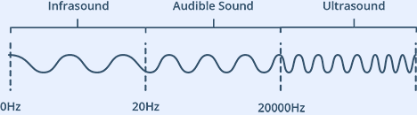
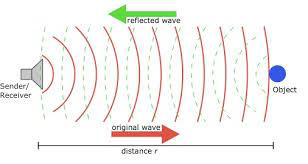
What is Ultrasound?
Ultrasound is a high-pitched sound wave whose frequency exceeds the audible range of human hearing.
Humans can hear sound waves that vibrate in the range of about 20 times a second (a deep rumbling noise) to 20,000 times a second (a high-pitched whistle). However, ultrasound has a frequency of more than 20,000 Hz and is therefore inaudible to humans.
One acts as a transmitter that converts the electrical signal into 40 KHz ultrasonic sound pulses. The other acts as a receiver and listens for the transmitted pulses.
When the receiver receives these pulses, it produces an output pulse whose width is proportional to the distance of the object in front.This sensor provides excellent non-contact range detection between 2 cm to 400 cm (~13 feet) with an accuracy of 3 mm.Since it operates on 5 volts, it can be connected directly to an Arduino or any other 5V logic microcontroller.
Technical Specifications
Here are the specifications:
Operating Voltage
DC 5V
Operating Current
15mA
Operating Frequency
40KHz
Max Range
4m
Min Range
2cm
Ranging Accuracy
3mm
Measuring Angle
15 degree
Trigger Input Signal
10µS TTL pulse
Dimension
45 x 20 x 15mm
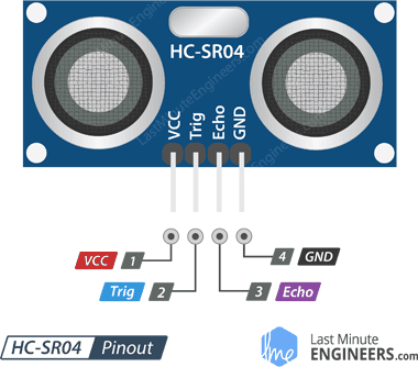
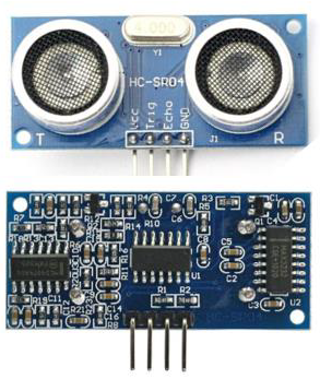
HC-SR04 Ultrasonic Sensor Pinout
Let’s take a look at its pinout.
VCC supplies power to the HC-SR04 ultrasonic sensor. You can connect it to the 5V output from your Arduino.
Trig (Trigger) pin is used to trigger ultrasonic sound pulses. By setting this pin to HIGH for 10µs, the sensor initiates an ultrasonic burst.
Echo pin goes high when the ultrasonic burst is transmitted and remains high until the sensor receives an echo, after which it goes low. By measuring the time the Echo pin stays high, the distance can be calculated.
GND is the ground pin. Connect it to the ground of the Arduino.
How Does HC-SR04 Ultrasonic Distance Sensor Work?
It all starts when the trigger pin is set HIGH for 10µs. In response, the sensor transmits an ultrasonic burst of eight pulses at 40 kHz. This 8-pulse pattern is specially designed so that the receiver can distinguish the transmitted pulses from ambient ultrasonic noise.
These eight ultrasonic pulses travel through the air away from the transmitter. Meanwhile the echo pin goes HIGH to initiate the echo-back signal.
If those pulses are not reflected back, the echo signal times out and goes low after 38ms (38 milliseconds). Thus a pulse of 38ms indicates no obstruction within the range of the sensor.
If those pulses are reflected back, the echo pin goes low as soon as the signal is received. This generates a pulse on the echo pin whose width varies from 150 µs to 25 ms depending on the time taken to receive the signal.
Calculating the Distance
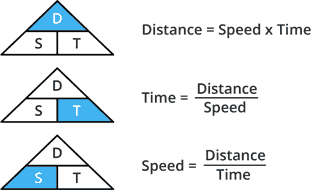
The width of the received pulse is used to calculate the distance from the reflected object. This can be worked out using the simple distance-speed-time equation we learned in high school. An easy way to remember the equation is to put the letters in a triangle.
Let us take an example to make it more clear. Suppose we have an object in front of the sensor at an unknown distance and we receive a pulse of 500µs width on the echo pin. Now let’s calculate how far the object is from the sensor. For this we will use the below equation.
Distance = Speed x Time
Here we have the value of time i.e. 500 µs and we know the speed. Of course it’s the speed of sound! It is 340 m/s. To calculate the distance we need to convert the speed of sound into cm/µs. It is 0.034 cm/μs. With that information we can now calculate the distance!
Distance = 0.034 cm/µs x 500 µs
But we’re not done yet! Remember that the echo pulse indicates the time it takes for the signal to be sent and reflected back. So to get the distance, you have to divide your result by two.
Distance = (0.034 cm/µs x 500 µs) / 2
Distance = 8.5 cm
Now we know that the object is 8.5 cm away from the sensor.
Required Materials
To follow along with this tutorial, you will need the following materials:
Disclosure: These are affiliate links. When you purchase through these links, we may earn an affiliate commission.
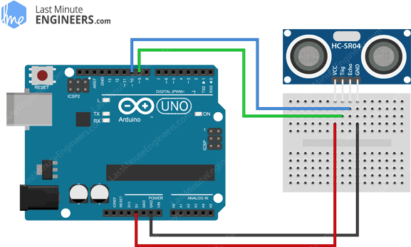
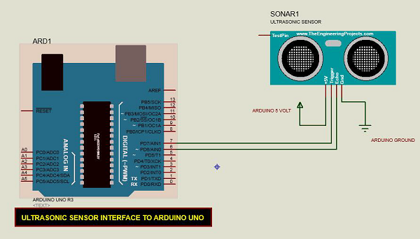
Wiring an HC-SR04 Sensor to an Arduino
Now that we have a complete understanding of how the HC-SR04 ultrasonic sensor works we can start connecting it to our Arduino!
Connecting the HC-SR04 to Arduino is very easy. Start by placing the sensor on your breadboard. Connect the VCC pin to the 5V pin on the Arduino and the GND pin to the ground pin. Now connect the trig and echo pins to digital pins #9 and #10 respectively.
The following table lists the pin connections:
HC-SR04 Sensor
Arduino
VCC
5V
Trig
9
Echo
10
GND
GND
When you are done you should have something that looks similar to the image shown below.
Wiring HC-SR04 Ultrasonic Sensor to Arduino UNO – Normal Mode
Library Installation
Triggering the ultrasonic sensor and measuring the received signal pulse width manually is a lot of work but luckily there are many libraries available to us. One of the popular libraries is the NewPing library. This is the library we will use in our examples.
The NewPing library is quite advanced. It supports up to 15 ultrasonic sensors at once and can output directly in centimeters, inches, or time periods.
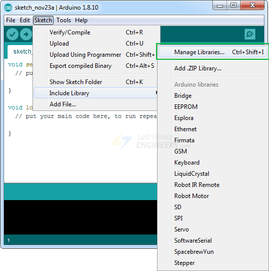
This library is not included in the Arduino IDE, so you will need to install it first.
To install the library navigate to Sketch > Include Libraries > Manage Libraries… Wait for Library Manager to download the library index and update the list of installed libraries.
Filter your search by typing ‘newping’. Click on the first entry and then select Install.
Arduino Example Code
Here is a simple sketch that uses the serial monitor to display a distance measured in centimeters. Give this sketch a try before we start a detailed analysis of it.
// Include NewPing Library
#include "NewPing.h"// Hook up HC-SR04 with Trig to Arduino Pin 9, Echo to Arduino pin 10
#define TRIGGER_PIN 9
#define ECHO_PIN 10
// Maximum distance we want to ping for (in centimeters).
#define MAX_DISTANCE 400
// NewPing setup of pins and maximum distance.
NewPing sonar(TRIGGER_PIN, ECHO_PIN, MAX_DISTANCE);
voidsetup() {
Serial.begin(9600);
}
voidloop() {
Serial.print("Distance = ");
Serial.print(sonar.ping_cm());
Serial.println(" cm");
delay(500);
}
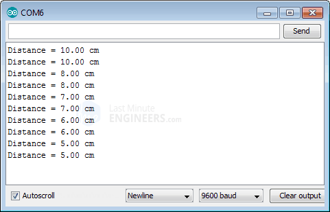
Once the sketch is uploaded, open your serial monitor, set the baud rate to 9600 bps. Try pointing the sensor at objects lying around you. You should see the measured distance begin to stream by.
Output on Serial Monitor
Code Explanation:
The sketch starts by including the newly installed NewPing library.
#include "NewPing.h"
First the Arduino pins are defined to which the Trig and Echo pins of the HC-SR04 are connected. We have also defined a constant called MAX_DISTANCE. It will set a maximum distance where pings beyond that distance are read as no ping “clear”. MAX_DISTANCE is currently set to 400 [default = 500cm].
In the setup, we initialize the serial communication with PC.
voidsetup() {
Serial.begin(9600);
}
In the loop, we simply call the ping_cm() function and print the result on the serial monitor. This function sends a ping and returns the distance in centimeters.
There are a few useful functions you can use with NewPing object.
Above sketch returns the distance in centimeters. If you want result to be in inches, use sonar.ping_in() function.
Serial.print(sonar.ping_in());
The sketch above only has a resolution of one centimeter. If you want to get the result in decimal form you can use NewPing in duration mode instead of distance mode. You need to change this line:
Serial.print(sonar.ping_cm());
with below line
Serial.print((sonar.ping() / 2) * 0.0343);
There is a method called ping_median(iterations) in the NewPing library to improve the accuracy of your HC-SR04. This method takes multiple measurements instead of just one, discards out-of-range readings, and then averages the remaining readings. By default it only takes 5 readings but you can specify as many as you want.
int iterations = 5;
Serial.print((sonar.ping_median(iterations) / 2) * 0.0343);
Arduino - Ultrasonic Sensor
The HC-SR04 ultrasonic sensor uses SONAR to determine the distance of an object just like the bats do. It offers excellent non-contact range detection with high accuracy and stable readings in an easy-to-use package from 2 cm to 400 cm or 1” to 13 feet.
The operation is not affected by sunlight or black material, although acoustically, soft materials like cloth can be difficult to detect. It comes complete with ultrasonic transmitter and receiver module.
Technical Specifications
Power Supply − +5V DC
Quiescent Current − <2mA
Working Current − 15mA
Effectual Angle − <15°
Ranging Distance − 2cm – 400 cm/1″ – 13ft
Resolution − 0.3 cm
Measuring Angle − 30 degree
Components Required
You will need the following components −
1 × Breadboard
1 × Arduino Uno R3
1 × ULTRASONIC Sensor (HC-SR04)
Procedure
Follow the circuit diagram and make the connections as shown in the image given below.
Sketch
Open the Arduino IDE software on your computer. Coding in the Arduino language will control your circuit. Open a new sketch File by clicking New.


No comments:
Post a Comment